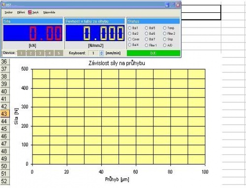
BST Program

The BST program provides user friendly GUI for the destructive testing of the materials.

The testing instrument is controlled by standalone electronic box with embedded controller SF6. This module executes all the hardware and time critical operations including the force measurement, hydraulic valve control and safety functions.

BST program accomplishes all the high level functions: visualization, specimen identification, definition and start of the test; processing of the measured data and saving the results in Excel. The Excel is used like an external module, except the running measurement the PC can be used like any other computer.


Protocol templates placed in separate folder define not only output protocol format, but they also include the dedicated measurement parameters in specified cells. Changing this cells content you can vary the instrument behavior during the measurement in a wide range. The measurement method features can be exploited and changed by a number of protocol templates referencing to the same method.

The measurement modes and parameters, data sampling functions and result calculation equations are defined in so called measurement methods. These standalone plug-in files written is C# enable an easy creating of the whole customer-defined solutions.

SF6 Controller

Controller SF6 is standalone HW module for the material testing instruments.

Based on a powerfull DSP with couple of special peripheries suported by gate array Xilinx Spartan solves all the time critical functions. Other functionality is provided by external CANopen modules like AD24 converter.

The implemented firmware supports both the electromechanical or hydraulic instruments running in the speed loop as well as the force loop. The touch of the specimen, safety functions and test finish conditions were implemented with special care.

The controller SF6 communicates with the host PC using standard USB, special driver makes accessible the controller functions for the GUI, e.g. BST software.

Inputs:   11 DI optoisol., 8 DI TTL (KEYB, etc..)  
Outputs:   12 DO relays, 8 DO TTL (LED, etc..)  
Encoders:   2 channels RS422  
PWM:   2 channels 10 bit (configurable 12 bit)  
Analog outputs:   PWM converted on 0-10V  

AD24 Converter

24 bit AD converter module for the force sensor connection. Input range 0-10 mV, output values are tansmitted via the CAN bus according CANopen DS-401.


Eltek spol. s.r.o. - © 2011
Galery | Admin |